Generatively Designed Motorcycle Frame
Overview
CAD design and additive manufacturing has changed drastically over the last 20 years. Generative design is one new innovation that takes advantage of the improvements in additive manufacturing, particularly with metals. I wanted to stay up to date with these new advances and improve my CAD skills, so I used the information I learned from a Fusion 360 generative design course to model a Ducati motorcycle chassis. I then used the models I generated to 3D print a scale mockup of the frame with a rear shock absorber. The frame is designed to be printed with metal using DMLS, but due to the cost of metal printing I printed the model with an FDM printer.

Processes Utilized
3D Modeling & Simulations (Fusion 360)
3D printing (FDM, DMLS)
Top Skills Utilized
Stress Analysis
Surfacing
Mechanical Design
DFAM

Process
Set Preserve Geometry (Mount locations on engine, axle, suspension, and steering)
Set Obstacle Geometry (Engine, wheels, steering, suspension, brakes, axle …etc)
Set Starting Geometry (Geometry to help the software start a solve towards a solution, used to speed up computations)
Set Loads (Braking, acceleration, lean left, learn right, and rear wheely for concept)
Set Design Objectives (Safety factor of 2.0, target mass, mesh resolution)
Set Material Options (Ex: Al 6061 Welded, Steel, and Titanium)
Set Manufacturing Constraints (Unrestricted, Additive, Milling, and Die-Cast)
Solve Simulation
Analyze Solutions (Check weight, mesh output, manufacturing technique, and then select the favorite option)
Convert mesh to 3D and check in Model (Check fitment and component mounting)
Prepare Mesh of Favorite Models for Simulations (Use surfacing to adjust mesh to eliminate stress concentrations and unnecessary curvature)
Run loading scenarios on frames to confirm stresses are acceptable.
Use frame model to mock up model to FDM print using Solidworks.
Prep and print motorcycle frame with Bambu Labs FDM printer.
Assemble Components


Simulation Setup

Frame Preserve Geometry

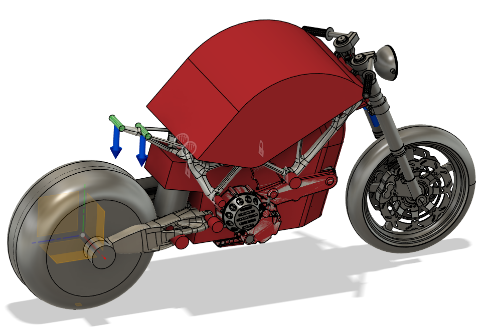
Rear Swing Arm Preserve Geometry
Set Preserve Geometry (Green)
-
Preserve Geometry was modeled for frame mounting locations.
Engine Mounts
Suspension Mounts
Rear Swing Arm Mounts
Steering Mounts

Set Starting Geometry (Yellow)
-
Starting Geometry was modeled to start the simulation solve and to speed up simulation time. Generic shapes can be used effectively to guide the solve.

Set Chassis Obstacle Geometry (Red)
-
Obstacle geometry was roughly modeled to act as keep out zones for the simulation. These chassis KOZs included:
Engine
Engine Mount Bolts
Fuel Tank
Suspension Bolts
Steering Assembly

Set Loads on Chassis
-
Loads were set to simulate scenarios the bike frame might see. Additional loading scenarios would need to be applied to fully cover loading ranges. The starting point for loads were determined from a Fusion 360 frame tutorial.
Braking Loads
Torsion acting on chassis from turning left and right
Acceleration Loads

Set Swing Arm Obstacle Geometry
-
Obstacle geometry was roughly modeled to act as keep out zones for the simulation. These swing arm KOZs included:
Tire + Wheel
Rear Axle
Rear Brakes
Suspension
Swing Arm Mounting Shaft
Chain
Set Design Objectives + Materials + Manufacturing
-
The simulation bounds were set to allow it to solve.
Safety Factor of 2.0
Coarser Mesh (Refined after initial solve)
Set to Maximize Stiffness
Set mass to 0.5 kg (Unrealistic, but it forces the simulation to remove as much material as possible)
Material
Aluminum 6061-O, AL 7075
Steel
Titanium
Manufacturing
Set as unrestricted to allow for additive manufacturing using metal powders.